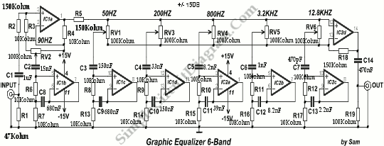


The most typical changes can be raising frequencies that are not available in the original music and eliminating undesired frequencies, such as noise. However, as detailed later in the article, the frequency range could well be easily changed, as desired, for this circuit.Ī high-gain, high-Q parametric equalizer is very effective for 'enhancing' recordings. The upper range spec of 11 kHz is also great as it decreases the chance of harming tweeters if the equalizer is set to a powerful boost at high frequencies (unless a correction is being done for a trough in the response). Since frequencies lower than 50Hz is mostly never preferred, the lower range specification of this circuit is excellent for the majority of the audio applications. The Gain and Q tests were taken at 1kHz, however the response uniformity was found to be superb over the whole frequency range. The boost and cut range specifications on the device were zero to slightly over 20dB, with a Q factor variable from 1 to 25, and a frequency range of 50Hz to 11kHz. The mentioned parametric equalizer is a high-performance gadget that may be used with even the most unconventional hifi system. Therefore, the circuit design discussed in this article can produce extremely beneficial results by enhancing the music input quality to outstanding levels. The main advantage of a parametric equalizer is that it allows you to modify the frequency and the "Q factor" across a wide range while also controlling the gain, which is not possible in most graphic equalizer circuits.įurthermore, in most cases, a couple of parametric equalizers per channel may outperform a complex graphic equalizer.


 0 kommentar(er)
